3DS Rotation Track Interpolation
Introduction
In this article I would like to explain how to do a proper interpolation of the rotation track used in 3DS 4.0 (in MAX this track is known as TCB rotation track - TCB comes from Tension, Bias, Continuity, which are the parameters affecting the spline).
I know that there have been many articles/doc's/sources that were dealing with this problem but unfortunately I couldn't find even one that was 100% correct, so I had to work the math out myself. :( Now I can say that I truely believe it's 100% correct. :)
Why was it so hard to do the proper interpolation of this kind of track? Mainly because the approach used in 3DS studio in some cases isn't math-derived - it seems to be constructed to give the best visual effects. Pity I couldn't find any information on how it is done - it was a real pain in the ass dealing with quaternions and unknown equations... But wait a minute, did I say......
Quaternions?
Well, to understand the following chapters you have to know some basics about them, so here it goes....
Quaternions were invented quite a long time ago by Sir Hamilton, an Irish aristocrat. Their purpose was to describe rotation in 3D-space. To do this we need four numbers - w,x,y,z. What are they? Well, it'll be enough to say the they form a kind of 4D vector - if you are really interested in this topic read [ 1 ], [ 2 ] and [ 6 ]. For us it's important how this vector is calculated.
The natural way to describe rotation is angle/axis notation - it represents rotation about the angle around the axis. Here we'll do some basic observations:
- rotating around any axis about an angle of 0 doesn't change the orientation of an object because it hasn't rotated (pretty obvious, huh? ;))
- rotation around an ( x, y, z ) axis about for example 10 degrees is the same as rotation around an ( -x,-y,-z ) axis about -10 degrees
Let's assume that the rotation axis has the length of 1 (it's a 3D unit vector). The quaternion representing the rotation is calculated like this:
q.w = cos(angle / 2)
q.x = axis.x * sin( angle / 2)
q.y = axis.y * sin( angle / 2)
q.z = axis.z * sin( angle / 2)
The resulting quaternion has the length of 1.
Right here we can see the first disadvantage of quaternions - they were created to represent the rotation about an angle lower than 2*PI - the quaternion for rotation about ( angle, axis ) is the same as for the rotation about ( angle + 2*PI, axis ).
Note that quaternion q still represents the same rotation that -q, just as in the angle/axis case.
So why do we need all those quaternions? Because it's very easy to accumulate rotations in the quaternion representation. If the object was rotated two times and the quaternion for the first rotation is q1 and for the second is q2 then the "overall" rotation is the result of multiplication of q1 by q2. This is done using the formulas below:
(Let treat the quaternion's x,y,z coordinates as a 3d vector v.)
q3 = q1 * q2
q3.w = q1.w * q2.w - q1.v * q2.v
q3.v = q1.w * q2.v + q2.w * q1.v + q1.v x q2.v
("q1.v * q2.v" is the dot product and "q1.v x q2.v" is the vector product)
Don't worry if these formulas seem wired (?) - it's enough to know that to multiply quaternions means to accumulate rotations. An important observation here is that if q1 and q2 were unit quaternions then q3 is the unit quaternion, too.
And what if we wanna know the difference between rotations (a relative rotation)? Well, you probably would like to use
q2 = q3 / q1
and that's what we'll do, we just have to write it in another way:
q2 = q3 * q1^(-1) q1^(-1) is an inverse quaternion - for an unit quaternion ( w , v ) the inverse quaternion is ( w, -v ).
There are several other operations that are possible with quaternions (look into [ 1 ]) but they really look abstract and aren't useful for our purposes.
Splines overview
A spline is a polynomial-based function. For each pair of control points we have a separate polynomial (usually of third degree - this means it looks like A*x^3+B^x^2+C*x+D=0).
When creating a spline between a series of points we have to consider the following two conditions:
a) the spline must be continuous
b) its deriverate must be continuous, too
Now maybe in English. :) The first condition tells us that the result of an interpolation must be one line - with no holes or breaks in it - we have to asure that the spline comes through all the control points.
The second condition tells us that satisfying the first one doesn't mean we have a spline. :) Doing it with linear functions couldn't be called a "smooth interpolation" - and that what the splines are about - "smooth".
There are many equations we can base our spline on (because being given only two points we can construct many polynomials satisfying both conditions). Later on we will use a little modification of the Hermite spline described by the equation
H(t) = p1*(1-t)^3 + c1*3t*(1-t)^2 + c2*3t^2*(1-t) + p2*t^3
p1 and p2 are the control points we want to guide our spline through. c1 and c2 are the tangents we can calculate when we know points p0 and p3.
But in 3DS we have the Kochanek-Bartels spline, which is an extension of the Hermite spline. It introduces three properties for every control point - tension, bias and continuity. Read in [ 3 ] and [ 5 ] for more about them.
Quaternion Splines
Interpolation of quaternions is more difficult than interpolation of a single value. The only thing we can use is slerp, which stands for Spherical Linear intERPolation. "What?" :) Well, we interpolate between two unit quaternions and we want the result to be a unit quaternion too. This means that they all lie on a 4-D sphere (don't try to imagine this :) - just treat it as a set of 4-D unit vectors).
The standard equation for linear interpolation is:
LInt(a,b,t) = a*(1-t) + b*t
And the one for spherical interpolation is similar:
slerp(q0,q1,t) = q0 * sin( (1-t)*a ) / sin(a) + q1 * sin( t*a ) / sin(a)
a is the angle between q0 and q1:
a = acos( q0 dot q1 )
and "q0 dot q1" is the dot product of 4-D vectors. Uff. :))))))))
When we take a look at the slerp equation we see that there will be some problems when the angle will be very close to or equal 0. In this case we have to do linear interpolation:
if ( fabs ( a ) < EPSILON ) return q0 * (1 - t ) + q1 * t
Now let's return to our spline. As we can only do linear interpolation we have to use formulas shown in [ 1 ] and [ 2 ]. These are:
squad(q0,q1,c0,c1,t)=slerp( slerp(q0,q1,t), slerp(c0,c1,t), 2t*(1-t) )
q0 and q1 are our control quaternions, c0 and c1 are our tangents multiplied by control points. The function 2t(1-t) for t=0 and t=1 has the value equal 0, so
squad(q0,q1,c0,c1,0) = q0 squad(q0,q1,c0,c1,1) = q1
and for t=0.5 the value is equal 0.5, so the result of squad lies (?) between the results of two previous interpolations (between q0 - q1 and between c0 and c1).
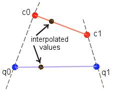
Let's try do draw what are we doing (all drawings will treat interpolation as a 2D function to make them look clear).
The first step is is the linear interpolation between q0 and q1 and between c0 and c1:
(time is 0.3333333)
Now we calculate the new interpolation value from 2*t*(1-t) and we get 0.4444444444444. We can do the final interpolation:
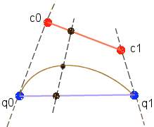
The black point in the middle is our final result, and this brown line is our interpolation track - it's really cubic despite the fact we use only linear interpolations. :)
Now we will look how these c0 and c1 are calculated. We will use reversed "Digisnap's notation". :) - For the control quaternion q "qb" represents the incoming tangent and "qa" the outgoing one. So when interpolating between q1 and q2 we will use:
squad(q1,q2,q1a,q2b,t)
The mathematical approach of calculating the tangents isn't as horrible as in seems when we take a first look at it, but still it has some limitations that we have to omit. So here comes...
3DS - specific stuff
Some of you probably know that 3DS stores the rotation track as an series of relative rotations in angle/axis format. The angles of those rotations are always positive. The first thing we should do is to convert them into quaternion representation. But as I said before quaternions are used to represent the rotations about angles smaller than 2*PI, so first we clip the angle:
clipped_angle = fmod ( angle, 2*PI )
and then we convert ( clipped_angle, axis ) into a quaternion. The last thing we do in this step is multiplying the quaternions to obtain absolute rotations:
quaternion = previous_quaternion * quaternion
Now maybe some words about calculating tangents. The first step of this formula that I found in the docs is:
q1 - previous quaternion
q2 - current quaternion
q3 = q1^(-1) * q2
q4 = log (q3)
The way we calculate this logarithm is:
_angle = acos(q3.w)
sn = sin(_angle)
coeff = _angle/sn
q4.w=0
q4.x = coeff*q3.x
q4.y = coeff*q3.y
q4.z = coeff*q3.z
When the angle is equal or very close to zero we will obtain some mess. :( And if the angle between q1 and q2 is greater than 2*PI the result will be incorrect. So this is where I had to do some modifications.
First take a look at the formula for for q3. Doesn't it look familiar? Of course it does! We calculate the relative rotation between q1 and q2. And in our case we know it (we had read it from *.3ds and then converted into a quaternion, remember?). So we can skip this step. Now let me remind you the way we have calculated our q3 from angle/axis:
q3.w = cos(angle / 2)
q3.x = axis.x * sin( angle / 2)
q3.y = axis.y * sin( angle / 2)
q3.z = axis.z * sin( angle / 2)
Now we put it into our equations for log( q3 ):
_angle = acos ( cos ( angle / 2 ) )
Hmmm. :/ Strange, isn't it? We can get rid of it. and more. we solve the problem with a rotation greater than 2 PI:
_angle = angle / 2
But let's take a look at the rest of a log() function:
                     _angle * q3.x
             q4.x = ---------------
                     sin ( _angle )

                    ( angle / 2 ) * q3.x
             q4.x = -----------------
                    sin ( angle /2 )
and q3.x = axis.x * sin( angle / 2), so:
                   ( angle / 2 ) * axis.x * sin ( angle /2 )
           q4.x = -------------------------------------------
                       sin (angle / 2 )

           q4.x = axis.x * angle / 2
Wow, never thought it would be so easy. :) And we got rid of this "angle close to 0" problem. :)
This is the mathematical solution, but when the angle is greater than 2*PI 3ds calculates it as if it was equal to PI (!):
q4.x = axis.x * PI / 2
This looks really strange, but this kind of tangent is needed for the formulas that 3DS uses for the interpolation of such case. And what is this case? Well, when the angle is equal or greater than 2*PI it looks like this:
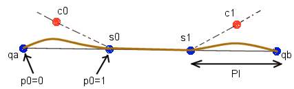
You may notice that we have 3 cases in such situation. First is the curve at the beginning, second is the straight line in the middle and third is the curve at the end. The point c0 and c1 are the tangents for this part of spline.
The points S0 and S1 are very important, because they always lie on the spline. S0 is the result of interpolation about PI around our rotation axis, and S1 is the resulting point of an interpolation about ( angle - PI ) around our axis. Some notes:
- when angle is equal to 2*PI the S0 is equal to S1
- tangent c1 does not affect the spline before point S1 and tangent c0 doesn't affect the spline after point S0; moreover, interpolation between S0 and S1 is linear - those two observations gave me an idea of existance of those points
Since the angle between qa and qb is greater than 2*PI, we cannot use Slerp for the calculation of S0 and S1. Fortunately we know the angle/axis between qa and ab, so we calculate two rotations (around PI and around ( angle - PI )), convert them into quaternions and the multiply qa by them to obtain absolute rotation. The same formulas are used for interpolation af the middle staright-line case.
The curves at the beginnig and at the end are interpolated in another way:
_p = Slerp ( qa, S0, p0 )
_q = Slerp ( A , S0, p0 )
q = Slerp ( _p, _q, 2*p0*( 1 - p0 ) )
The second curve is calculated in a similar way. Saying the truth I found those formulas by an accident. :P
The source is in the bonus for this issue of Hugi, so there you can find all this stuff working. Check this out.
Final words
Well, I have to thank the persons listed below. Without their help/work I wouldn't be able to code all this stuff. Here it goes in alphabetical order:
| Acid | - for his help when I was doing my first steps in this topic |
| Adept | - for the spline_?.zip series - I found many solutions there |
| Borzom | - the author of clax |
| Dave Eberly | - thanks for a great help and for the |
| www.magic-software.com service | - I've found many useful documents and sources there |
| Digisnap | - great article in Hugi#12 about 3DS splines |
| MRI | - for his 3ds reader and format description |
Big thanks go to all of them and to you for getting through all the stuff about. :) I you have any question about the topic check out the bibliogaphy listed below, try out the source or try to throw an e-mail at me.
Bye
P.S. E-mail account may be dead during the summer-time....
Bibliography
[ 1 ]  Erik B. Dam, Martin Koch, Martin Lillholm
                 "Quaternions, Interpolation and Animation"

[ 2 ] David Eberly
           "Quaternion Algebra and Calculus"

[ 3 ] David Eberly
            "Kochanek-Bartels Cubic Splines"

[ 4 ] David Eberly
           "Key Frame Interpolation via Splines and Quaternions"

[ 5 ] Digisnap
        "Splines & Quaternions"

[ 6 ] Ken Skoemake
            "Quaternions"

[ 7 ] hexapod@netcom.com
	"The Matrix and Quaternions FAQ"